We've been so anxious in getting the F150 completed, we haven't had time to keep you up-to-date on our progress.
To continue where we left off, before we paint the knuckle, the rear steering stop has to be cut off to allow for more turning radius. The reason for this is that the lower control arm is so beefy is actually cuts down on the turning room. so off it comes.
As you can see we've sprayed some rock guard on the knuckle and installed the new upper Heim Joint. Then we test fit everything to make sure we've got the proper clearances.
Finally our King Racing Shocks have arrived!!
We hooked up with King Racing out of California about a month ago, Gave them some specs in what what we were needing and they took it from there.
For the fronts we're using the 2.5" x10" Performance Race Series, 800lb rated coils with remote reservoirs. As for controlling the compression travel we're adding 2.5"x4" Bump Stops stroked to 3" with a 1" internal spacer.
This will provide a very smooth compression stop.
For the rears we went for the OE Performance Series piggyback shocks. Since we're keeping the rear suspension stock, we've kept the shock travel the same length. We'll also add some rear bumps stops to it as well to cushion the compression travel.
In the instructions it calls for the upper coil retaining collar to be 2-1/2" down from the top of the thread. After we set this we tried installing it and there was no way we were able to compress the coil to attach the lower a-arm. So we backed it off enough that we can get it all hooked up. We'll play around with that retainer collar later as it sets the ride height profile once the truck is sitting on it's own weight.
Time to install the coil over. Start by routing the reservoir through the top shock tower.
In order to attach the lower a-arm to the shock mount, we had to use a couple of tie-down straps to help compress the coils in order to bolt them together. Being 800lb rated it's not something you can do by hand.
To prevent and damage from over extending the suspension travel, we installed a limiting strap to control that.
Next thing on the list, the steering linkage needs to be addressed. Supplied in the kit is a tie-rod extension link. it basically attaches between the tie-rod and steering linkage.
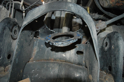
Time to mount up the KING 2.5" Bump Stops. First we had to determine where we wanted the compressed suspension to stop before we rip off the fenders when landing a jump. Once we marked this out, it's time to get a little creative with the mounts.
First we tack weld the bump stop sleeve to our location
Next we add some added 3/16" support plates to both side of the sleeve and welded them up to the frame.
the only thing left to do is put in the 2.5" KING bump stop and paint it all up.


